
What a truly wicked week of weather! With the frequent wind and snowstorms, you’d think that there’s been no flying at all. However, being a stalwart group, a few of us did venture out last Saturday for a trip to the Vulcan RCAF strip and lunch at Linden. Unfortunately, outside of that, this month has been slow on the flying front.
Work has been a different matter. We’ve had a pair of Diamond DA-42 Twin Stars with diesel engines in for work. These are beautiful airplanes, complete with the Garmin G-1000 (I think they should have called it the G-Whiz) system and full FADEC engine systems. Fuel economy is incredible at only about 5 gph per side! However, they are a bit cantankerous to start in the cold.
We also had an Aztec in for an avionics upgrade. With Canadian Avionics being a bit short-handed, I got an opportunity to help out with the installation. In doing so, I learned a neat new trick for dealing with shielded wire installation.
In the past, I, like many builders, carefully stripped away the outer insulation and then combed out the shielding wire. This can take a couple of attempts, as invariably, the shielding wire has been nicked and the strands pull away. Once the shielding wire had been successfully combed to the side, it was twisted, covered with heat shrink, and a terminal installed on the end. At best, it looked OK, albeit a bit amateurish in appearance.

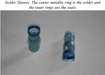
This month I learned a far better method of doing this with the use of solder sleeves. Solder sleeves consist of a heat-shrinkable, transparent sleeve with an inner, pre-fluxed solder preform and two thermoplastic sealing inserts. When heat is applied, the solder melts and flows. At the same time, the two thermoplastic sealing inserts melt, and the outer sleeve shrinks to provide an environmentally protected termination.
To use the sleeves, strip away the outer shielding back as far as you need to work with the inner core wire. Trim the shielding mesh back to within ¼” of the end of the outer cover. Next, cut the outer shielding about ½” from the end and slide it up to the end of the exposed shielding mesh, leaving ¼” of shielding visible behind it.

A length of #18 wire long enough to reach from the shielding to the ground point can now be prepared by stripping off ¼” of insulation. The exposed end of the #18 wire along with the end of the shielded wire are slipped inside the solder sleeve together so that the exposed piece of shielding mesh, the end of the #18 wire, and the solder inside the solder sleeve are adjacent to each other.
The final step is to heat the sleeve up using a heat gun. Make sure that you see the solder melt inside the sleeve to ensure an adequate connection inside the sleeve. See the last two pictures. Now the appropriate terminal can be placed on the end of the ground wire and you’re ready to go.
